Guides / Process
Load Lock and Transfer Chamber Parts: What Is Machined and What Is Toleranced
October 17, 2026
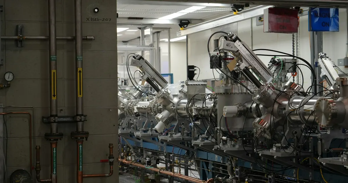
Wafers move from air into vacuum through a load lock and then ride a robot through a transfer chamber to the process chambers. Both are plain-looking machined bodies, but they carry some of the tightest seal and flatness requirements on the tool.
This guide covers what each does, which parts get machined and which dimensions the drawing has to control.
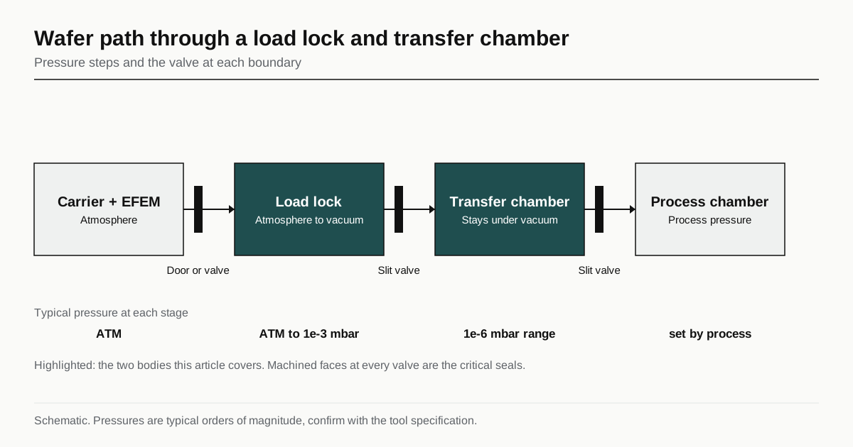
How the two chambers work
Load lock. A small chamber with a door to the atmosphere side and a valve to the vacuum side. A wafer enters, the atmosphere door closes, the chamber is pumped down, the vacuum side opens and the robot takes the wafer. On the way out the chamber is vented with clean dry gas. This cycle repeats for every wafer or every cassette, so the chamber is kept small to pump down quickly, and its inner surfaces are finished to avoid trapping gas.
Transfer chamber. A larger chamber that stays under vacuum and houses a wafer handling robot. Process chambers and load locks attach to its sides through slit valves. Most of the machined work here is the body itself, the mounting for the robot and the openings around the sides.
The valve between chambers is covered in the guide to slit valve and gate valve components.
Parts on an RFQ
An RFQ for this class of equipment usually lists some of the following parts.
| Part | Typical material | What the drawing controls |
|---|---|---|
| Transfer chamber body | 6061 or 5083 aluminum, or 316L | Flatness of side faces, slit opening position, bore for the robot |
| Load lock body | 6061 aluminum, sometimes 316L | Internal volume, port position, sealing faces |
| Lid or top plate | Aluminum, stainless steel | Flatness, O-ring groove, viewport openings |
| Robot mounting plate | Aluminum, stainless steel | Flatness, hole pattern, positional tolerance |
| Wafer shelf and cassette lift | Aluminum, stainless steel, ceramic | Slot pitch, parallelism, edge finish |
| Heater or cooler plate | Aluminum, stainless steel | Contact flatness, channel leak rate |
| Vent and pump port parts | Stainless steel | Port size, weld preparation, threads |
Material choice is a design decision. Aluminum is lighter, easier to cut and conducts heat, while stainless steel is stronger and gives lower outgassing in some surface conditions. The trade-off is covered in the guide to aluminum vs stainless for vacuum chamber parts, and the plate stability question for large bodies in the guide to MIC-6 aluminum plate for chambers.
Dimensions that matter most
Position of the openings. The slit openings must land where the robot expects the wafer to pass, so position is toleranced against a datum on the body, not just a size. A tolerance of a few tenths of a millimeter is typical, with the figure coming from the tool.
Flatness and parallelism of the mating faces. Each opening has a sealing face where a valve or a chamber attaches. Typical figures are 0.02 to 0.05 mm flatness over the face and a parallelism relative to the opposite face that is stated on the drawing. A body that is out of flat by more than the seal can take leaks, and a tighter number than the seal needs adds cost.
Robot bore and mounting. The robot sits on a plate or in a bore at the center, and its axis is positioned against the openings. The hole pattern and the flatness of the plate affect how well the arm can reach a wafer position, so these are also toleranced against a datum.
Internal finish. The inside of a load lock should be smooth and free of pockets that trap gas. Typical values for internal faces are Ra 0.8 to 1.6 micrometers for machined surfaces, with finer values on sealing faces. Blind holes should be avoided or vented, as in the guide to vented screws and vacuum fasteners.
Monolithic body or welded assembly
A transfer chamber can be machined from a single plate or block, or fabricated from plates welded together.
A monolithic body has no welds to leak and holds the relationship between openings in a single setup family. The cost is the amount of material removed and the size of machine needed, and a large block can move as stress is released, so roughing, stress relief and finishing are separate operations.
A welded body uses less material and can be cheaper at large sizes. It has to be leak tested and often stress relieved, and flatness of the faces is machined after welding. The choice of weld process is covered in the guide to TIG vs E-beam welding for vacuum parts.
For either form, ask the shop for the machine travel, the largest similar part it has made and how it controls distortion. The cost drivers for large bodies are laid out in the guide to chamber and wafer handling part costs.
Seals, grooves and leak testing
Every opening has a seal. The groove geometry and the sealing face finish follow the rules in the guide to O-ring groove machining. On a load lock door, the seal sees a lot of cycles, so the groove edge break and surface finish matter for seal life.
Leak testing is part of acceptance for chamber bodies. A typical callout for a high vacuum transfer chamber is in the 1e-9 to 1e-8 mbar L/s range, with the tool deciding. The test method and condition of the part go on the drawing, as described in the guide to helium leak testing for chamber parts.
Surface treatment and cleaning
Aluminum chamber bodies are often anodized, bare or electroless nickel plated, depending on the process the chamber sees. The treatment changes the final size, so the drawing says whether tolerances apply before or after. Stainless parts may be electropolished or passivated, and cleaning follows a stated process.
Cleanliness for load lock parts is usually strict because they sit near the wafer path. Drawings ask for precision cleaning, a stated particle or residue limit and clean packing. The wording follows the rules in the guide to cleanliness and surface finish for vacuum parts.
Venting and pumping features
A load lock is cycled thousands of times, so its gas paths matter. The vent port brings in clean dry gas, often through a diffuser so the flow does not blow particles around, and the pump port is sized for the pump-down time the tool needs. Machined features include the port bores, the diffuser seat and the weld preparation for the connecting tubes. Sharp edges at port entries are broken, since a burr in a gas path sheds. The drawing should state port sizes, thread or flange type and the sealing standard of each connection, and should mark any internal pocket that needs venting.
Lead time and what to expect
Large chamber bodies take longer to quote than most parts. Material may be a plate or a forging with a lead time of its own, and machining can run for many hours on one part. Weeks of lead time are common on large bodies, with the number depending on the supplier. Ask the shop what is in the quote: material, machining, stress relief, leak test, cleaning and packing.
Checklist before the RFQ
- Part type and material, with the plate or forging form if it matters.
- Position tolerance of the openings against named datums.
- Flatness and parallelism of each sealing and mating face.
- Internal finish, blind hole policy and vent requirements.
- Leak rate, test method and the state of the part at test.
- Surface treatment and whether tolerances apply after it.
- Cleaning, protection and packing.
Send the drawing with those items stated. It goes to up to three shops that already run large vacuum bodies, and a reply comes within 24 business hours.
Frequently asked questions
Are the load lock and the transfer chamber one part or two?
Both are possible. Many tools use separate bodies bolted together, and some are machined as one monolithic block with several chambers. The drawing and the RFQ should say which, because a monolithic block is a single large machining job.
Why is a chamber body machined from plate and not welded?
A body machined from a single plate or block has no weld seams to leak and holds the faces in one setup relationship. A welded body is cheaper for large sizes but needs a leak test after welding and stress relief to hold flatness.
What size of machine does a transfer chamber need?
It depends on the tool. A body for a cluster tool can be hundreds of millimeters across with deep pockets and several slit openings, so ask the shop for the travel and the largest part it has made.
Have a part like this?
Send the drawing. We match it with up to 3 shops that already run semiconductor equipment parts and reply within 24 business hours.
Send my RFQ