Guides / Process
Helium Leak Testing for Machined Vacuum Chamber Parts: What the Drawing Has to Say
October 16, 2026
A vacuum part can be dimensionally perfect and still be scrap, because it leaks. The helium leak test is how that gets found before the part ships, and it only works as a check if the drawing says what to test, how and against which number.
Most disagreements about leak tests are not about helium. They are about a missing line: the leak rate with no units, the method left open, or no word about whether the part is tested before or after cleaning.
How the test works
Helium is used because the atom is small, it is inert, and there is very little of it in normal air, so a mass spectrometer tuned to helium has a quiet background. The part is connected to a leak detector that pumps it down. Helium is then applied to the outside, and any helium that finds a path through a weld, a seal or a pore is pulled into the detector and counted.
The reading is a leak rate, a quantity of gas per second at a defined pressure. The two units you will see are mbar L/s and atm cc/s. One atm cc/s is about 1.013 mbar L/s, so the numbers are close but not identical, and a drawing that leaves the unit out can be read two ways. Write the unit.
A calibrated leak is the reference. Before the test the operator checks the detector against a leak of known rate, and the report should show that check. A leak test without a calibration record is just a reading.
Which method fits which part
There are three methods in routine use, and they do not detect the same thing.
| Method | How the part is set up | Typical use |
|---|---|---|
| Vacuum, spray or probe | Part evacuated, helium sprayed on the outside | Chamber bodies, flanged parts, weld seams |
| Vacuum, hood or bag | Part evacuated inside an enclosure filled with helium | Whole-part leak check, final acceptance |
| Sniffer | Part filled with helium under pressure, probe moved over the outside | Parts that cannot be pumped, location of a known leak |
The spray method finds where a leak is. The hood method tells you the total. The sniffer method is the least sensitive, and typical figures for it sit several orders of magnitude above a good vacuum test, so it cannot prove a UHV acceptance number. If the drawing asks for 1e-9 and the shop proposes a sniffer test, the method does not match the requirement.
Practices exist for the probe methods, among them ASTM E498 and E499, and ISO 20485 covers sniffing. Name the practice you want and check the current edition rather than relying on a copy from an older job.
Typical leak rate callouts
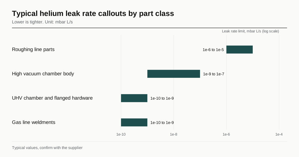
The right number comes from the tool, not from habit. The ranges below are typical drawing values, not promises, and the tool specification wins.
| Part class | Typical callout, mbar L/s | Comment |
|---|---|---|
| Roughing line parts | 1e-6 to 1e-5 | Tolerant, often a bubble or pressure decay check |
| High vacuum chamber body | 1e-9 to 1e-7 | Depends on chamber volume and pump speed |
| UHV chamber and flanged hardware | 1e-10 to 1e-9 | Needs a clean setup and a stable detector |
| Gas line weldments | 1e-10 to 1e-9 | Internal weld, tested after welding |
A tighter number costs more, because the test takes longer and the setup has to be cleaner. Ask for what the tool needs and no tighter.
What causes a false reading
Not every helium signal is a leak in the metal. A short list explains most of the surprises.
- Virtual leaks. A blind tapped hole, a screw in a blind hole or a sealed cavity between two welds holds gas that bleeds out slowly. It looks like a leak and is really a design problem. This is why vented screws and through holes show up on vacuum hardware.
- Elastomer permeation. Helium passes through elastomer O-rings. A seal that is fine for gas retention can still show a helium rise during the test, so the test seals and the service seals are not interchangeable.
- Contamination. Oil, water or solvent in a thread or a pore can plug a real leak for a while and then release. A part that passes wet can fail dry.
- Porous material. Cast aluminum and poor welds can seep through porosity that a short test does not catch.
A good test report notes the setup, the seals used on the test fixture and the background level of the detector before the part was connected.
Where in the process the test belongs
The sequence changes the result. Three points are worth writing down.
- Test after welding, before final finishing. A weld seam is easier to find and repair before it is covered. Anodize and some coatings can close small leaks temporarily, so a leak found after coating may reappear later.
- Test before precision cleaning, then clean. Helium testing is done on a part that is reasonably clean, but the final clean and pack follows the leak test. If cleaning and packing come first, opening the bag to test defeats them. See the cleanliness and finish rules for how those notes should read.
- Repair means retest. If a weld is reworked, the part goes back on the detector. The drawing should say that a repaired part is retested to the same number.
Welded parts also depend on joint design and process choice, covered in the guide to TIG and electron beam welding for vacuum parts.
Fixtures and ports
A part has to be sealed to the detector somehow. That needs a blank plate, an O-ring or a bellows and sometimes a purpose-made fixture. A flange face that is also the sealing surface should not be marked by the fixture, so say which faces may be clamped against. For a part with several openings, the RFQ should list every port and state which are sealed with blanks and which are left open for the test.
Test fixtures are a quote line. A one-off part with an odd port layout needs a fixture that the shop has to make, and that cost belongs in the price rather than turning up later.
The five lines for the drawing
A vacuum part is quotable for leak testing when these are present.
- The leak rate limit and its unit, for example 1e-9 mbar L/s.
- The test method: vacuum with spray, hood, or another named one.
- The tracer gas and, if it matters, the concentration and the test pressure difference.
- The condition of the part at test: after welding, before coating, before cleaning.
- The report: leak rate, date, detector calibration check and part serial number.
If one of these is missing, the shop fills the gap with its normal practice. That is a reasonable reading of an incomplete drawing, and it is also how a part passes the test and leaks in service.
Reading the report and handling a failure
A leak test report should let a second person judge the result without asking questions. The useful fields are the measured leak rate, the detector background before the part was connected, the value of the calibrated leak used for the check, the test method, the helium concentration, how long the part was held before the reading and the part identification.
The background number matters because a leak rate is only meaningful against it. A part that reads 5e-10 on a detector with a background of 4e-10 has not shown a leak rate of 5e-10, it has shown that the test cannot resolve that number. If the drawing asks for 1e-9, the detector background has to sit well below it.
When a part fails, the operator locates the leak by spraying helium in small steps. Helium is lighter than air and rises, so the standard practice is to start at the top of the part and work down, otherwise a leak at the top is flooded while testing the bottom. Once the leak is found, the repair depends on the cause:
- A weld defect is ground out and rewelded, then the part is retested to the full requirement.
- A porous casting or plate may not be repairable, and the material choice is the fix.
- A damaged sealing face is remachined if stock allows, which changes a dimension the drawing may control.
A repaired part that is not retested is not a repaired part. Add one line to the drawing: repaired parts are retested to the same limit and the report is updated.
Cost and lead time
Leak testing shows up in a quote as time on the detector, a fixture and sometimes an outside service. The time depends on the volume of the part, because a larger volume takes longer to pump down and longer for the helium signal to rise and clear between sprays. A small flange tests in minutes. A large chamber body can take an hour or more, and a tight number takes longer than a loose one.
Two questions in the RFQ save a round of emails. Who performs the test, and where. If the shop sends parts out for testing, the lead time carries a shipping loop and the cleanliness plan has to survive it.
Next step
Before sending an RFQ, check the five lines against your drawing and mark who performs the test if the shop does not have a detector. Then send the drawing and state the leak rate requirement in the RFQ form notes. It goes to up to three shops that already run this class of part, and a reply comes within 24 business hours.
Frequently asked questions
Can a machine shop run the helium leak test itself?
Some can, most cannot. A mass spectrometer leak detector is a separate capital item and many shops buy the service from a specialist. Ask in the RFQ who performs the test and where, because the answer changes both the price and the lead time.
Is a leak rate of 1e-9 always tight enough?
It depends on the chamber volume, the pump and the process. A number that is fine on a roughing line can be far too loose on a UHV tool. Take the value from the tool specification, not from a previous drawing.
Why did a part pass the shop test and leak at the customer?
The usual causes are a different seal at the customer, a part that was cleaned or coated after the test, or a trapped volume that only shows up once the part is under vacuum for hours. The drawing should say what condition the part is in when it is tested.
Have a part like this?
Send the drawing. We match it with up to 3 shops that already run semiconductor equipment parts and reply within 24 business hours.
Send my RFQ