Guides / Process
EFEM Frames, Plates and Robot Brackets: Machining the Front End of a Tool
October 13, 2026
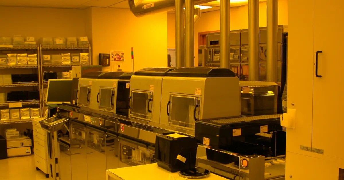
An Equipment Front End Module sits at the front of a semiconductor tool. Wafer carriers dock at its load ports and a robot moves wafers between the carriers and the tool behind. It is the atmospheric side of a tool and so looks simpler than a vacuum chamber, but the parts have to hold positions to a fraction of a millimeter and keep the air clean.
This guide covers what the machined parts are, which tolerances matter and what the drawing should say.
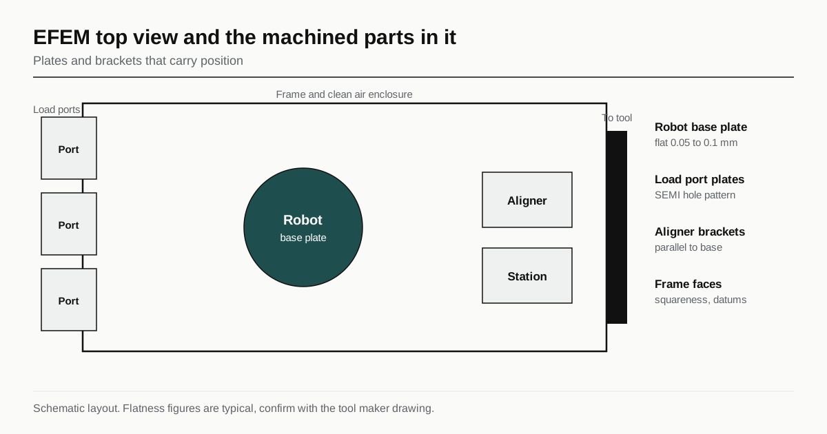
What an EFEM contains
A typical module holds four groups of items.
- A frame that carries everything and keeps it square. It may be welded steel, stainless sheet metal or an aluminum structure.
- Load ports on the front, where carriers dock and open. Their mounting faces are tied to published dimensions.
- A wafer handling robot on a base plate near the center.
- An aligner and other stations, and a fan filter unit at the top that sends clean air downward.
Most of the machined parts are plates and brackets that join these groups. The frame is often fabricated by a sheet metal shop, and the machining work is on the plates, interface faces and brackets.
Machined parts and typical materials
| Part | Typical material | What the drawing controls |
|---|---|---|
| Robot base plate | 6061 or MIC-6 aluminum, stainless steel | Flatness, hole pattern position, thickness |
| Load port interface plate | Aluminum | Hole pattern, face flatness, position vs datum |
| Aligner and station brackets | Aluminum, stainless steel | Position, parallelism, edge break |
| Frame corner and leveling parts | Steel, stainless steel, aluminum | Hole size and position |
| Panels and covers | Aluminum sheet, stainless sheet | Flatness, fit, finish |
| Ceiling and filter interface | Aluminum | Flatness, sealing face for filter gasket |
Aluminum dominates because it is light and cuts fast. Where plates must stay flat over time, the stock matters, as in the guide to MIC-6 aluminum plate for chambers. Stainless steel is chosen for corrosion resistance or where a wet clean process is nearby.
Interfaces that follow a standard
The load port interface is where the EFEM meets the carrier. SEMI standards define the mechanical interface and carrier dimensions for 300 mm wafers: E15.1 for load ports, E47.1 for the carrier and E62 for the interface. These standards fix hole patterns, datum surfaces and sizes, so a plate that attaches the port to the frame must hit those positions. Check the current edition of the relevant SEMI standard before quoting it, and take the real values from the tool maker’s drawing.
The practical point is that some dimensions are not negotiable. If the drawing carries a standard feature, a shop treats the stated tolerance as the limit and does not loosen it for convenience.
Tolerances that matter
Robot base plate flatness and position. The robot arm reaches into carriers and aligners that sit at set distances from its base. If the plate is not flat the base tilts, and every taught position shifts with it. Typical callouts are 0.05 to 0.1 mm flatness over the plate, with the hole pattern positioned to a few hundredths of a millimeter. The tool maker decides the exact numbers.
Parallelism and perpendicularity. Brackets for aligners and stations must sit parallel to the base so wafers pass level. Where a bracket stands on a plate, perpendicularity to the base is drawn, and a long tall bracket needs a rigid cut plan so it does not spring.
Hole position and fit. Dowel holes locate parts against each other, and clearance holes must line up on assembly. Positional tolerances in a dowel pattern are tighter than those for a clearance hole, and the drawing says which is which.
Edge condition. A burr in a part near the wafer path sheds particles and can scratch. Edges are broken to a stated size, and exposed corners are rounded.
Measurement for plates and brackets uses a CMM or a surface plate, described in the guide to CMM and flatness reports for chamber parts.
Surface treatment and cleanliness
EFEM parts are in clean air but not vacuum. Common treatments are:
- Hard or clear anodize on aluminum, which gives a hard, stable surface that does not shed. The drawing states the type, thickness and whether tolerances apply after anodizing.
- Black anodize on parts near optical sensors, to cut reflection.
- Powder coat or paint on frame panels, where particle shedding is controlled by the process and a cure step.
- Electroless nickel on some steel and aluminum parts, for wear and corrosion resistance.
Static control also matters. Wafers are damaged by static discharge, so grounded parts need a conductive path. Anodize is an insulator, so the drawing marks areas that stay bare for grounding.
Parts are cleaned and packed so they enter a clean assembly area without extra work. The wording follows the guide to cleanliness and surface finish for vacuum parts, with less strict limits than in a vacuum chamber.
Rigidity and vibration
A robot accelerates its arm and the load shows up as vibration in the frame. A bracket that is too thin or too long resonates, and the robot then settles slowly after each move. Thin parts are cheap to machine but expensive in tool time. Drawings often include a minimum thickness and a rule against removing material from ribs, and a part maker can suggest ribs where the design allows.
Plate parts also change shape with temperature. Aluminum expands more than steel, so a long aluminum plate on a steel frame needs slotted holes, or a joint that can move. If the drawing has fixed holes at both ends of a long plate, ask whether the design allows for thermal movement.
Weldments and sheet metal
Frames and panels often come from sheet metal shops. For weldments, flatness and squareness after welding are limited by distortion, so a stress relief and a finish machining step on interface faces are common. A weld that is machined after welding needs enough stock, and the drawing should state it. Weld practice for stainless parts follows the guide to TIG vs E-beam welding for vacuum parts, though without the vacuum leak requirement.
Fasteners, dowels and assembly
Robot plates and brackets are bolted and doweled in place, and the way they are joined decides how repeatable the tool is. Dowel holes are reamed to a fit and positioned against the datums, while clearance holes for bolts are looser. Sunk or counterbored screw heads sit below the surface so they do not catch a wafer carrier or an arm. Thread inserts in aluminum are common on parts that are removed for service. State the fastener standard and torque on the drawing or an assembly note, and mark any hole that must stay bare for grounding.
Cost drivers
An EFEM part is rarely expensive alone, but the set is: dozens of plates and brackets, each with its own setup and surface treatment. Price falls with batch size because programs and fixtures are shared. The ordering of operations also matters: a plate that is machined, anodized and then re-machined on its datum face costs more than one with tolerance stated after anodize. The wider picture is in the guide to chamber and wafer handling part costs.
Checklist before the RFQ
- Part list with material and stock form for each plate.
- Flatness, position and parallelism for robot and load port interfaces, with datums named.
- Which features follow a SEMI standard, and the edition.
- Surface treatment, thickness and bare areas for grounding.
- Edge break and burr rules near the wafer path.
- Inspection method and report.
- Cleaning, packing and quantity.
Send the drawing with a part list and those notes. It goes to up to three shops that already machine this class of part, and a reply comes within 24 business hours.
Frequently asked questions
What does EFEM stand for?
Equipment Front End Module. It is the enclosure at the front of a process tool where wafer carriers dock at load ports and a robot moves wafers between the carrier and the tool, under filtered air.
Is an EFEM a vacuum part?
No. It works at atmospheric pressure, with filtered air flowing down through it. The parts are therefore not leak tested, but cleanliness, flatness and position still matter.
Why does a robot bracket need a tight tolerance?
The robot learns positions relative to its base. If the bracket or plate is out of flat or its hole pattern is off, the arm starts from a different reference and the taught positions drift. A flat, stable mounting is cheaper than constant re-teaching.
Have a part like this?
Send the drawing. We match it with up to 3 shops that already run semiconductor equipment parts and reply within 24 business hours.
Send my RFQ