Guides / Process
CMP Tool Parts: Carrier Head Components and Retaining Ring Machining
October 12, 2026
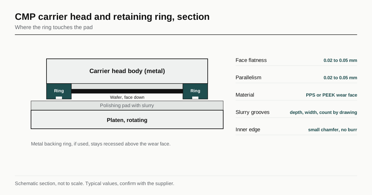
In chemical mechanical planarization the wafer is pressed face down against a spinning pad with slurry between them. A carrier head holds the wafer, and a ring around it keeps it from sliding out. That ring touches the pad, wears, and is replaced often. For a machine shop it is a clean plastic part with a few critical dimensions.
This guide covers the ring and the metal parts of the carrier head: materials, grooves, tolerances and the cleanliness the drawing has to ask for.
What the ring does
During polishing the wafer is pushed sideways by friction with the pad. The ring surrounds it and holds it in place. It also does a second job: it presses on the pad around the wafer so the pad is compressed evenly at the wafer edge. That is why ring pressure is a process setting, and why the ring face has to be flat and parallel to the head.
Slurry has to reach the wafer, so the ring has channels in its bottom face. They let fresh slurry flow under the ring and toward the wafer and allow used slurry out. Channel pattern, depth and width are part of the process, and the tool maker specifies them.
Materials
The face that touches the pad is plastic. The common choices are:
| Material | Typical use | Notes |
|---|---|---|
| PPS (polyphenylene sulfide) | Common wear ring material | Stable, chemical resistant, moderate wear rate |
| PEEK | Wear rings that need higher strength | Tougher, costs more, machined with more care |
| Other engineered plastics | Special processes | Chosen by the tool maker for the slurry and pad |
A plastic ring avoids metal ions that would contaminate the wafer. For stiffness, some designs bond or screw the plastic ring to a stainless steel or titanium backing ring. The metal must be recessed and covered so it never touches the pad or the slurry, and the fastener holes are positioned so the screws sit below the wear limit.
Plastic properties and machining behavior are covered in the guide to PFA, PVDF and PEEK for wet process tools, and most of it applies here: sharp tools, light clamping, annealed stock and attention to heat.
Dimensions that matter
The ring is a simple shape, so the tolerance matters more than the geometry. Typical callouts are below. They are not promises, and the tool specification wins.
| Feature | Typical callout | Why it matters |
|---|---|---|
| Bottom face flatness | 0.02 to 0.05 mm | Even pressure on the pad |
| Parallelism, bottom to top | 0.02 to 0.05 mm | Ring sits level in the head |
| Inner diameter | per the tool drawing, a small clearance over the wafer | Holds the wafer without pinching |
| Ring thickness | per the tool drawing | Sets wear life, thickness checked at several points |
| Groove depth and width | per the tool drawing | Controls slurry flow |
| Edge break on inner edge | small stated radius or chamfer | A sharp edge chips the wafer edge |
Because plastic moves with temperature and stress, flatness and thickness are measured at a stated temperature after the ring has rested. The measurement approach follows the guide to CMM and flatness reports for chamber parts, with a gentle hold so the part is not distorted by the fixture.
Slurry grooves
Grooves are cut with a milling cutter or a form tool. Burr control is the main issue: a burr at a groove edge chips off into the slurry and scratches a wafer. Plastic burrs are stringy and hard to see, so the drawing should state that grooves are deburred and ask for inspection under magnification. The groove corners are drawn with a radius so slurry does not stagnate and so a cutter can make them cleanly.
Groove pattern tolerance has two parts: the shape of each groove and the spacing around the ring. A rotary table with a stable indexing method holds the spacing, and the program should cut in a sequence that releases stress evenly.
Metal parts of the carrier head
The head body, base plate, and mounting parts are metal, usually stainless steel or aluminum. They hold the membrane that presses on the wafer and the air channels that give each zone its pressure. The machined features include:
- Air and vacuum channels with fine cross holes that open into zones. Burrs inside them block flow or release particles, as in the guide to gas showerhead machining.
- Sealing faces for membranes and O-rings, with the groove rules in the guide to O-ring groove machining.
- Mounting flanges with a bolt pattern and a flat face to attach to the spindle.
- Exposed surfaces that see slurry, which are coated, anodized or made from corrosion resistant steel.
Slurry is chemically aggressive, so metal parts that touch it need a coating or a resistant alloy. Typical choices are stainless steel with passivation, or hard anodize on aluminum. The treatment is named on the drawing, with a statement on whether tolerances apply after it.
Cleanliness
CMP is a cleaning-sensitive process, and carrier head parts go near the wafer. Typical notes cover:
- Cleaning in deionized water, with a stated ultrasonic step and a final rinse.
- No oil-based coolant on plastic parts, as it soaks in.
- Drying in a clean environment and packing in a sealed bag or tray.
- No marking on the wear face. Part numbers go on a non-wetted face or on the bag.
- A residue or particle limit only if the tool needs one.
The wording follows the guide to cleanliness and surface finish for vacuum parts, though CMP parts work at atmospheric pressure and do not need a vacuum bake.
Wear measurement and acceptance
Ring wear is tracked by thickness. A new ring has a stated thickness, and a wear limit marks the point at which it must be replaced. Many designs include a groove depth that doubles as a wear indicator, since a ring whose slurry grooves have worn away no longer moves slurry as designed. The drawing should state the new thickness with its tolerance, the groove depth at the start of life and the limit at which the ring is scrapped. Incoming inspection by the user is usually a thickness measurement at several points around the ring, plus a visual check of the wear face.
Wear life and cost
A retaining ring is a consumable, and tool users buy it in batches. Two things drive price: the stock and the machining time for the grooves. Virgin resin stock with a lot certificate costs more than commodity stock, and the groove program takes machine time. A batch shares setup, so unit price falls with quantity. A spare set is cheaper than a one-off.
If a ring is a replacement for a part from the tool maker, say so in the RFQ and send the original drawing. A shop quotes against the drawing, and the buyer is responsible for qualification on the tool.
Checklist before the RFQ
- Ring material, grade and form, with a lot certificate.
- Bottom face flatness, parallelism and thickness, measured at a stated temperature.
- Inner diameter and edge break.
- Groove pattern with depth, width, count and deburring rule.
- Metal backing ring and fastener details, if the ring has them.
- Cleaning, packing and quantity.
Send the drawing with those lines. It goes to up to three shops that already run this class of part, and a reply comes within 24 business hours.
Frequently asked questions
Why are retaining rings made of plastic?
The ring touches the polishing pad and wears. A plastic wear face avoids metal contamination of the wafer and the slurry, and it wears evenly. The ring is a consumable that is replaced on a schedule.
Do the slurry grooves have to match the original exactly?
They control how slurry reaches the wafer edge, so groove count, width, depth and angle are part of the polishing process. The drawing from the tool maker gives them and a shop should not change them.
Are retaining rings made in one piece?
Both forms exist. Some are a single plastic ring. Others are two pieces, a plastic wear ring joined to a metal backing ring for stiffness. The joint and the fasteners are drawn, and the metal must not reach the pad.
Have a part like this?
Send the drawing. We match it with up to 3 shops that already run semiconductor equipment parts and reply within 24 business hours.
Send my RFQ